This is a first introduction to chiptuning for the 2.2L z22se ecotec engine in the Opel Speedster and Vauxhall vx220. How a engine management worksThere are lots of stories about “chiptuning”, lots of different claims about power, torque, driveability etc. Based on all the experience I’ve got with the engine management on the 2.2L engine in the Opel Speedster I wrote this article on how this engine management works. The engine management is nothing else then a computer with lots of connections. Just like a PC it can’t do anything without software. On a PC commonly software like Windows or Linux (the operating system) is used combined with different applications. An engine management doesn’t need to have such broad features as a PC. Almost all functionality that is available in a PC is redundant for an engine management. But the basic idea remains the same. The engine management has an operating system, just like a PC. But it is not written to be used with all kinds of different applications. There are different software modules though which can be added, depending on the kind of car the engine management is in (for example ABS, ESP, cruise control etc.). The engine managements software is not stored on a hard disk like with a PC, but is stored on a chip. Often it is possible to install a new version of the software on this chip (for example to fix bugs). This isn’t as easy as with a PC, it usually requires some dedicated equipment, often available only at dealers. [ecu.nl.jpg hoofdbrandstoftabel.png hoofdbrandstoftabel.thumb.png lft-en.png lft-en.thumb.png lft-tabel.png lft-tabel.thumb.png lft.png lft.thumb.png manifold.nl.jpg openloop-en.png openloop-en.thumb.png openloop.png openloop.thumb.png sft-en.png sft-en.thumb.png sft.png sft.thumb.png targetafr.nl.jpg]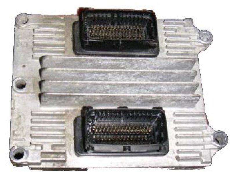 The way the software in the engine management works can be the same for a range of different engines, for example a 1.6, 1.8 and 2.0. But the way the engine management needs to control these engine is of course different. To prevent each engine of having a specific version of the software, the specific values for the different engines are stored in tables. This tables for example have information on the amount of fuel the engine management needs to add depending on the engine RPM and the throttle position. The content of these tables differ from engine to engine, as the amount of fuel needed to keep a 1.6 engine running is different from a 2.0. Changing these tables is a lot easier and safer then having to make different versions of the software. And this is exactly what chiptuners do, they change the values in these tables. A different term for table is of course map, hence the term remapping. What happens during chiptuningThe goal with chiptuning is often to get more power from the engine. To be able to get more power from an engine, you need to add something which can provide this power. With a combustion engine this is fuel, in case of the 2.2L engine, gasoline. To be able to burn the gas, oxygen is needed which is contained in the air. To be able to get the most powerful combustion an engine needs a specific ratio of air and fuel. So just adding more fuel will not help, more air needs to be added too. With a turbo engine this is a relatively easy job for the tuner. On modern turbo engine the engine management controls the turbo pressure. By raising the turbo pressure, the amount of air is increased. By adding more fuel, more energy is released during combustion and the engine delivers more power. This explains the difference in claimed power increases between normal (atmospheric) and turbo engines. But even with an engine like the 2.2L, it is possible to get more power by making sure that the engine is effectively running the best air fuel ratio to provide maximum power. The engine maker usually is on the safe side with the air fuel ratio because of the world wide different conditions the engine has to perform in. By further optimising the air fuel ratio some power can be gained. What happens when changing the engineAn example of a popular change for the 2.2L engine is to change the intake manifold for a better one. The standard intake manifold is a restriction for this engine, it does not deliver enough air. By changing the intake manifold the engine will be able to suck in more air, thereby adding more fuel and delivering more power. [ecu.nl.jpg hoofdbrandstoftabel.png hoofdbrandstoftabel.thumb.png lft-en.png lft-en.thumb.png lft-tabel.png lft-tabel.thumb.png lft.png lft.thumb.png manifold.nl.jpg openloop-en.png openloop-en.thumb.png openloop.png openloop.thumb.png sft-en.png sft-en.thumb.png sft.png sft.thumb.png targetafr.nl.jpg]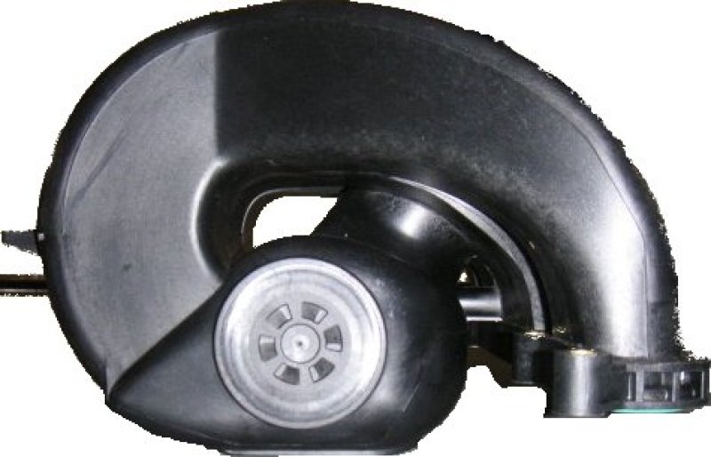 But there are different results when placing a different intake manifold (discarding the difference in intake manifolds being used). This can be explained by the way the engine management works. Making the mixtureLets assume 1 simple table in the engine management which contains the throttle valve position on the y-axis and the engine RPM on the x-axis. Each cell in this table contains a value. These values indicate the amount of fuel the engine management needs to add for this specific combination of throttle and RPM. [ecu.nl.jpg hoofdbrandstoftabel.png hoofdbrandstoftabel.thumb.png lft-en.png lft-en.thumb.png lft-tabel.png lft-tabel.thumb.png lft.png lft.thumb.png manifold.nl.jpg openloop-en.png openloop-en.thumb.png openloop.png openloop.thumb.png sft-en.png sft-en.thumb.png sft.png sft.thumb.png targetafr.nl.jpg]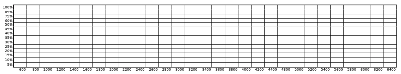 After changing the intake manifold, the same throttle position will allow in a different amount of air. So if the same amount if fuel is still used, the air to fuel ratio will not be correct anymore. The least this will impair the engine performance, but in extreme cases it can damage the eninge. There are of course more subtle situations where the amount of oxygen entering the engine for a specific throttle position is different. Think about changes in the air temperature and pressure, but also engine wear. To be able to compensate for these kind of situations a special mechanism is built into the engine management. This mechanism uses an oxygen sensor (also known as a lambda sensor) in the exhaust system. Through this sensor the engine management is able to determine the amount of oxygen left in the exhaust gases. If the ratio between air and fuel is optimal, the amount of oxygen left in the exhaust gases will be minimal. For gasoline the optimal ratio between fuel and air is 1 to 14.7, so there is exactly enough air for the amount of fuel, and the burn process is complete. The sensor in the exhaust will indicate to the engine management if the ratio was lower then 1:14.7 (too much fuel for the amount of air) or lower then 1:14.7 (too little fuel for the amount of air). How much the ratio differs from 1:14.7 can not be determined by the signal from this sensor. During operation of the engine, the engine management will continuously try to get the lambda sensor as close to 1:14.7 as possible. The engine management read the fuel value from the main fuel table, and checks the last reading from the lambda sensor. If the signal indicates too little fuel, an extra addition will be made and vice versa. This way the engine management continuously tries to optimise the air to fuel ratio. These changes in the ratio are called trims. As these trims are taking place quite quickly, they are known as short term fuel trims (SFT). This changes take place in a loop like process, which is known as closed loop operation. [ecu.nl.jpg hoofdbrandstoftabel.png hoofdbrandstoftabel.thumb.png lft-en.png lft-en.thumb.png lft-tabel.png lft-tabel.thumb.png lft.png lft.thumb.png manifold.nl.jpg openloop-en.png openloop-en.thumb.png openloop.png openloop.thumb.png sft-en.png sft-en.thumb.png sft.png sft.thumb.png targetafr.nl.jpg]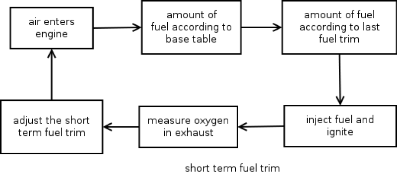 The process of trying to optimise the value from the base fuel table is not optimal. The changes are reactive, the loop needs to be traversed a couple of times to get the changes right, and this takes time. To save time and have a better initial air to fuel ratio the engine management creates a temporary table in memory. Depending on engine operating conditions the engine management will fill this table with deviations on the base fuel table. The advantage of this setup is that the amount of fuel will now directly be corrected without having to look at the lambda sensor first. This table contains fuel trims that are collected over a longer period of time. Therefor it is called a long term fuel trim (LFT). [ecu.nl.jpg hoofdbrandstoftabel.png hoofdbrandstoftabel.thumb.png lft-en.png lft-en.thumb.png lft-tabel.png lft-tabel.thumb.png lft.png lft.thumb.png manifold.nl.jpg openloop-en.png openloop-en.thumb.png openloop.png openloop.thumb.png sft-en.png sft-en.thumb.png sft.png sft.thumb.png targetafr.nl.jpg]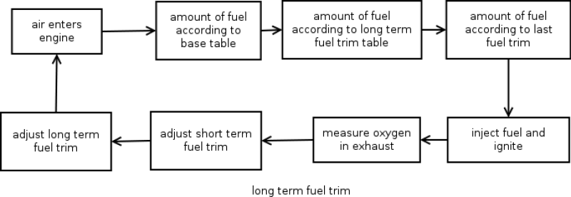 The engine management in our engine has a luxury LFT. It consists of a table with multiple cells. This table isn’t as large as the base fuel table. But there are also engine managements which work with only 1 LFT value for all operating conditions. For a standard engine this isn’t much of a problem. For variations in weather and engine wear such a table adequate to compensate the changes in fueling. The engines character is still the same, and this character is what is embedded in the fueling information stored in the base fuel table. [ecu.nl.jpg hoofdbrandstoftabel.png hoofdbrandstoftabel.thumb.png lft-en.png lft-en.thumb.png lft-tabel.png lft-tabel.thumb.png lft.png lft.thumb.png manifold.nl.jpg openloop-en.png openloop-en.thumb.png openloop.png openloop.thumb.png sft-en.png sft-en.thumb.png sft.png sft.thumb.png targetafr.nl.jpg]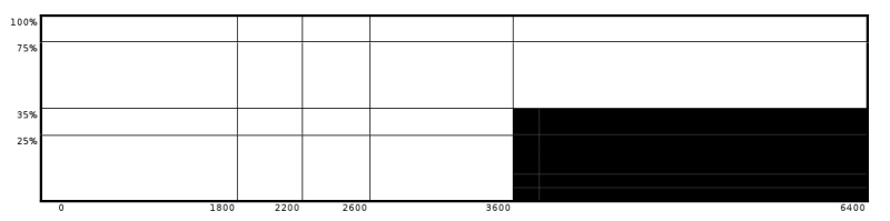 The difference with the base fuel table is pretty clear. The base fuel table has over 350 cells. The LFT table only has 18 cells. Now the situation where the intake manifold is placed. This gives a significant change in the character of the engine. The flow of the intake manifold differs with RPM’s. The trim mechanism in the engine management will of course still work, but due to the character change in the engine it is very difficult to fit all these changes in the small LFT table. Especially the cells in the LFT table that account for a large operating range of the engine will change often, because one of those cells needs to compensate for a whole range of different fuelings. Basically, the values in the LFT table are never correct. More powerTo get the engine to deliver maximum power a different fuel to air ratio is needed then 1:14.7. More fuel needs to be added to make maximum power. For the engine management this is quite straight forward. The engine management has been programmed that on full throttle (so delivering maximum power) it needs to deliver an air to fuel ratio of 12.6:1. Because the engine management knows how to make an air to fuel ratio of 14.7:1 (through the base fuel table and all the trims) it can calculate how much fuel needs to be added to make a ratio of 12.6:1. This type of air to fuel ratio is also know as a target air to fuel ratio or a target AFR. The word target indicates that the engine management can’t be sure the AFR is correct. The lambda sensor in the exhaust isn’t able to indicated the engine management how far the air fuel ratio is below 14.7:1. So there is no way for the engine management to verify. No loop is active anymore to verify and control the exact air to fuel ratio, so this mode of operation is also know as open loop. [ecu.nl.jpg hoofdbrandstoftabel.png hoofdbrandstoftabel.thumb.png lft-en.png lft-en.thumb.png lft-tabel.png lft-tabel.thumb.png lft.png lft.thumb.png manifold.nl.jpg openloop-en.png openloop-en.thumb.png openloop.png openloop.thumb.png sft-en.png sft-en.thumb.png sft.png sft.thumb.png targetafr.nl.jpg]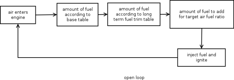 From the information above it is quite clear that it is very important that the engine management accurately knows how to make a 14.7:1 air fuel ratio. When changing the intake manifold, this will no longer be the case. The LFT table contains a cell which covers almost half of the RPM range on full throttle. The chance this cell contains the correct value for this whole operating range is 0. Therefor the engine management will not be able to make the required target AFR and so the engine will not deliver full power. Below a power graph can be seen for an Opel Speedster. The lower graph is for a target AFR of 12.7:1, the higher graph is for an AFR of 12.9:1. [ecu.nl.jpg hoofdbrandstoftabel.png hoofdbrandstoftabel.thumb.png lft-en.png lft-en.thumb.png lft-tabel.png lft-tabel.thumb.png lft.png lft.thumb.png manifold.nl.jpg openloop-en.png openloop-en.thumb.png openloop.png openloop.thumb.png sft-en.png sft-en.thumb.png sft.png sft.thumb.png targetafr.nl.jpg]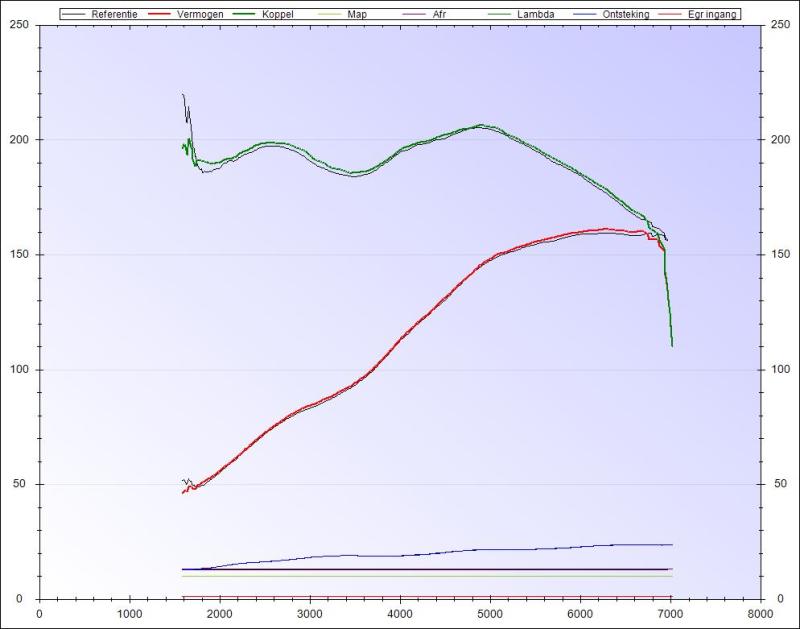 Such tiny changes in AFR give a reproducible change in engine performance and signifies the importance of an accurate target AFR. ConclusionAn engine management has a compensation mechanism that is able to compensate for weather influences and engine wear for an engine which has the same character as the engine management was calibrated for. This compensation can be done with a table which is much coarser then the base table. When changing the engine’s character, the LFT table is too coarse to compensate for the character changes. The cells in the table are too large. This causes the engine to not operate optimally and in extreme cases can lead to damage. The performance for the engine will not be optimal. Depending on the current values in the LFT table, the performance can be different from measurement to measurement and can be quite significant. The solution for this is to modify the base fuel table in the engine management so each position in the table contains the correct amount of fuel for a 14.7:1 air to fuel ratio. This way the engine management will be able to make the target AFR and the engine will deliver optimal power. When optimally chiptuning an engine management it is not possible to optimize the base fuel table on one engine and copy it to another engine. The base table is dependant on the state of the engine, including all modifications and will be different with different engine modifications. |